Arista Networks A-D400-Q400-20M Compatible 400G QSFP112 4 x 100G PAM4 to 400G QSFP-DD 8 x 50G PAM4 Active Optical Cable, 20m (66ft)
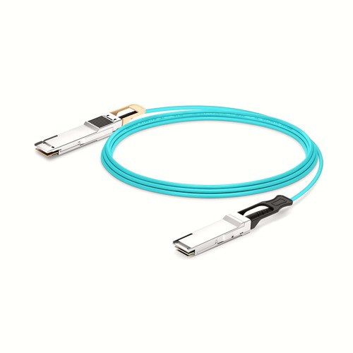
The A-D400-Q400-20M compatible AOC cable provides 400G connectivity for Arista Networks equipment over a fixed 20m (66ft) assembly. Both ends use the stated QSFP112 to QSFP-DD arrangement. It is inspected and functionally checked before packing, with handling guidance designed to protect the connectors during installation and later service.
OEM Part Number: A-D400-Q400-20MHT Part Number: A-D400-Q400-20M
Product Highlights
- Compatible alternative to Arista Networks A-D400-Q400-20M
- 400G connectivity at 400Gbps
- Interface configuration: QSFP112 to QSFP-DD
- Fixed length and part number: 20m (66ft), A-D400-Q400-20M
- Cable construction: AOC
- Maximum power consumption: 10W (QSFP112 End) 14W (QSFP-DD End)
- Minimum bend radius: 30mm
Specifications
| HT Part Number | A-D400-Q400-20M |
|---|---|
| Arista Networks Compatible | A-D400-Q400-20M |
| Manufacturer | HT |
| Form Factor | QSFP112 to QSFP-DD |
| Max. Data Rate | 400Gbps |
| Cable Length | 20m (66ft) |
| Cable Type | AOC |
| Wavelength | 850nm |
| Minimum Bend Radius | 30mm |
| Transmitter Type | VSCEL |
| Receiver Type | PIN |
| Max. Power Consumption | 10W (QSFP112 End) 14W (QSFP-DD End) |
| Jacket Material | OFNP |
| DSP | TX & RX Built-in DSP |
| DDM/DOM | Supported |
| Modulation Format | QSFP112-4x 100G-PAM4QSFP-DD-8x 50G-PAM4 |
| Commercial TemperatureRange | 0 to 70°C (32 to 158°F) |
| Protocols | QSFP112 MSA, QSFP-DD MSA, IEEE802.3ck, IEEE802.3bs, CMIS 5.1 |
Signal and Lane Configuration
The listed modulation format is QSFP112-4x 100G-PAM4QSFP-DD-8x 50G-PAM4. Both host interfaces must be configured for the same aggregate rate and lane arrangement. A connector that fits mechanically does not by itself guarantee that the remote port supports this encoding or breakout mode.
Power and Thermal Planning
The rated power consumption is 10W (QSFP112 End) 14W (QSFP-DD End). Include this load in the host-port power and thermal budget, especially in densely populated switches. Maintain front-panel clearance and do not bundle the cable so tightly that it obstructs airflow around the connectors.
Cable Construction and Routing
This assembly uses OFNP jacket, minimum bend radius 30mm. These mechanical characteristics affect how the cable should be dressed behind the equipment. Avoid sharp edges, excessive ties and repeated tight bends close to the connector boots.
Network and Protocol Considerations
The intended application is determined by the host interface and protocol support. Listed interface and protocol references include QSFP112 MSA, QSFP-DD MSA, IEEE802.3ck, IEEE802.3bs, CMIS 5.1. Confirm that the host firmware and port configuration support the same operating mode.
Integrated Optical Assembly
The optical engines and fiber are permanently integrated into this AOC. There are no detachable optical modules to clean or exchange. Handle the complete assembly by its connector housings and cable, and keep both ends matched to the same interface specification.
Length Selection and Installation Planning
The 20m (66ft) reach of A-D400-Q400-20M is useful only when the managed pathway requires it; straight-line distance between ports is not a sufficient measurement. Check the route around rack rails, cable managers and maintenance clearances, then protect the integrated optical cable and both optical engines from tight bends and unsupported spans. Within this family, A-D400-Q400-15M is shorter at 15m (49ft), while A-D400-Q400-25M is the next longer choice at 25m (82ft); comparing those two boundaries helps avoid both tension and unnecessary slack.
Position Within the Length Range
A-D400-Q400-20M occupies the middle of this family between A-D400-Q400-15M at 15m (49ft) and A-D400-Q400-25M at 25m (82ft). It adds 5m over the shorter option for extra routing clearance, while the next longer version adds another 5m. Measure the managed path and choose this version when its reach is sufficient without creating the slack associated with the longer assembly.
Field Installation and Maintenance
Inspect the route and both connectors before installation, then support the cable without pulling on either connector housing. During maintenance, release the latch properly rather than using the cable as a handle. Keep protection on unused ends, and if the assembly is removed for later use, coil it loosely and record its part number so the same length can be returned to service. For this assembly, the minimum bend radius is 30mm; the stated power consumption is 10W (QSFP112 End) 14W (QSFP-DD End); the jacket material is OFNP.
Quality Assurance and Packaging
The cable and both connectors are inspected before a functional link test. Connector protection and bend-safe packing reduce handling damage during transport and storage. Customer or site labels can be added for field inventories, with different lengths separated to simplify issue and return of spare assemblies. Neutral packaging and customer-specific packing documentation are available on request.
Arista Networks Compatibility and Factory Testing
A field-ready cable needs both correct identification and a stable operating link. Our pre-packing check therefore includes the connectors, host recognition and link behavior. For equipment with uncertain revision history, providing the host model and software release helps identify compatibility requirements before the assembly reaches the installation site. Both connectors are examined before the operating test, which includes receive activity and diagnostic indications.
Frequently Asked Questions
Is this an original Arista Networks cable?
No. It is an HT-manufactured compatible alternative for equipment that specifies Arista Networks A-D400-Q400-20M.
Will any matching connector operate at the same speed?
Not necessarily. Both hosts must support the stated rate, identification, lane mapping and any required breakout configuration; mechanical compatibility alone is insufficient.
What details assist a compatibility review?
Provide the equipment manufacturer, model, port type, hardware revision and software release, together with the OEM reference, required length and quantity.
How should an unused assembly be stored?
Protect both connector ends, keep the cable in a loose bend-safe coil and retain its part-number label so the length and compatibility identity remain traceable.
Ordering Information
Request the cable by its exact part number and length, and state the equipment model if compatibility confirmation is needed. Site orders can list quantities by rack or installation team. Any requested label should retain the part number so a removed or spare cable can still be identified accurately. Quantity and any labeling instructions should be attached specifically to A-D400-Q400-20M.
Shipping and Lead Time
Standard configurations normally ship within one to three working days, while production quantities are confirmed with the order. Delivery can be arranged by courier, air freight or sea freight, and goods may instead be handed to an appointed forwarder or shipped on the customer’s courier account.


