LC/APC Single Mode Fixed Fiber Optic Attenuator, Male to Female, 1-25dB
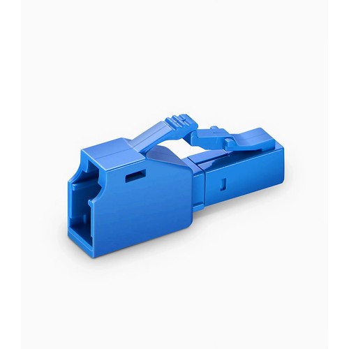
For Tanzanian site work, correct product selection should be followed by careful transport, connector inspection and retention of the fiber records. LC/APC Single Mode Fixed Fiber Optic Attenuator inserts a precisely calibrated fixed loss into a fiber connection. The attenuating element is ion-doped fiber - the loss is spectrally flat and reflection-free, unlike air-gap or offset designs - so the connection sees exactly the rated attenuation at every operating wavelength. The male-to-female plug body attaches directly to the rack-mounted panel adapter or transceiver port, adding attenuation without an extra patch cord in the route.
Product Highlights
- Attenuating Material-ion Doped Fiber
- 1260 to 1620nm Wavelength Singlemode Attenuators
- Precision Polishing for Reduced Back Reflection
- Standard Fixed Attenuation Values of 1dB up to 25dB
- Applied for CWDM, DWDM, Test Equipment, CATV Systems, Point to Point Systems, etc.
Specifications
| Fiber Connector | LC/APC |
|---|---|
| Polish Type | APC |
| Connector Gender | Fixed Male to Female |
| Attenuation | 1~25dB |
| Operating Wavelength(nm) | 1260~1620 |
| Operating Temperature Range | -25 to 70°C (-13 to 158°F) |
| Storage Temperature Range | -40 to 85°C (-40 to 185°F) |
| Application(1) | Matching Product(1) |
| Return Loss | ≥60dB (APC) |
Available Attenuation Values
The LC/APC fixed attenuator is available across the full standard range: 1dB, 2dB, 3dB, 4dB, 5dB, 6dB, 7dB, 8dB, 9dB, 10dB, 11dB, 12dB, 13dB, 14dB, 15dB, 16dB, 17dB, 18dB, 19dB, 20dB, 21dB, 22dB, 23dB, 24dB, 25dB. Every value is individually calibrated at 1310 nm and 1550 nm and the rated figure is marked on each housing, so the ordered value is exactly the installed value. State the required figure - for example LC/APC 10dB - with the enquiry.
1dB 2dB 3dB 4dB 5dB 6dB 7dB 8dB 9dB 10dB 11dB 12dB 13dB 14dB 15dB 16dB 17dB 18dB 19dB 20dB 21dB 22dB 23dB 24dB 25dB
Attenuation in testing and calibration
Beyond live links, attenuators are the reference instruments of the fiber lab. Receiver sensitivity is measured by adding loss until errors appear; power meters are calibrated against known attenuation values; a new transceiver type is qualified across its receive range before installation. Fixed attenuators incorporate the stable reference points, and variable attenuators sweep the range between them. Both must hold their rated figure over wavelength and temperature, which is what separates a calibrated device from a decorative one.
Spectral flatness across the operating band
An attenuator that reads 10 dB at 1310 nm but 12 dB at 1550 nm is a measurement error waiting to happen. The ion-doped element in these attenuators is engineered for spectral flatness across the full 1260 to 1620 nm window, covering every common operating wavelength from legacy 1310 nm links through DWDM C-band and L-band systems. One device therefore serves the whole plant instead of one wavelength plan. For Tanzanian site work, keep this requirement with the field checklist and the delivered product records.
Fixed values versus a variable instrument
Fixed attenuators win on stability, size and price: once the requested loss is known, a fixed device holds it permanently with no moving parts. Variable attenuators win when the loss itself is the question - receiver sensitivity testing, margin surveys, multi-wavelength leveling - where sweeping the figure is the whole point. Most plants need both: fixed units installed in the links, and a variable instrument in the test kit.
Choosing the attenuation value
The right figure is the difference between what the connection delivers and what the receiver wants, plus a small margin. Measure or calculate the expected receive power first; then choose the nearest standard figure - 1, 2, 3, 5, 7, 10, 15, 20 or 25 dB - that lands the receiver inside its window. Too little attenuation leaves the receiver overloaded; too much eats the margin that aging and repairs will need later. When the specification sits between standard values, the customized platform covers the precise figure.
Male-to-female plug attenuators in practice
The plug-style body turns the attenuator into a connector accessory rather than a cable unit: the male end seats directly in the rack-mounted panel adapter or the transceiver port, and the existing patch cord mates to the female end. No extra jumper, no extra mating pair, no extra loss beyond the rated figure. In dense frames this matters twice - once in the optical link budget, and once in the supplied cable management behind the rack-mounted panel.
Return loss and the polish discipline
An attenuator sits in the middle of the connection; thus, its reflectance counts twice - once toward the transmitter and once toward the receiver. UPC versions hold return loss at 50 dB or better, and APC versions at 60 dB or better, which keeps reflected power far below anything a modern transmitter notices. The polish grade should be matched to the plant: an APC attenuator mated to a UPC connector through an adapter damages both end faces and destroys the very return loss it was specified to protect.
Handling and cleaning attenuators
An attenuator is a connector with optics inside, and connector rules apply: keep the caps on until the moment of mating, clean every end face before insertion, and never mate a contaminated ferrule into the device - the dirt transfers to the attenuator end face and the next connector that touches it. Store spare units capped and bagged, and record which connection each installed unit serves so replacement orders match the original figure.
Selecting the right attenuator
Four decisions define the order: the attenuation figure should be matched to the connection calculation, the connector being used series should be matched to the port or the patch cords, the polish grade should be matched to the plant, and the body style - plug or inline - must suit the installation. Fixed values cover permanent installations; the variable instruments cover testing; the test cable covers transceiver qualification. Getting all four right at order time is what turns a small component into a dependable part of the connection.
Factory Quality Control and Testing
Every attenuator is optically verified before packing: the attenuation figure is measured at the operating wavelengths and checked against its rated tolerance, return loss is verified to its polish grade, and the connector being used end faces are inspected for scratches and contamination. Units ship capped and bagged.
Purchase and Factory Support
Refer to this attenuator by attenuation figure, connector series, polish grade and body style when purchasing a quotation. For values or configurations outside the listed options - non-standard dB figures, mixed connector pairings or project packaging - send the specification with the request and the factory will ensure the manufacturable specification. For Tanzanian deliveries, the order details should include any site identification needed by the installation team.


