Intel QDD-FR4-400G Compatible 400G QSFP-DD FR4 Transceiver Module
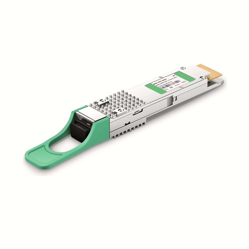
This Intel QDD-FR4-400G compatible transceiver provides 400G connectivity in a hot-swappable QSFP-DD package. Its optical design operates at 1271nm,1291nm,1311nm,1331nm for up to 2km, using Duplex LC/UPC. Complete parameters and related OEM references help field technicians install, maintain and identify the exact compatible module.
OEM Part Number: QDD-FR4-400GHT Part Number: QDD-FR4-400G
Product Highlights
- Compatible alternative to Intel QDD-FR4-400G
- 400G connectivity at 400Gbps
- Optical wavelength: 1271nm,1291nm,1311nm,1331nm
- Specified reach: 2km
- Duplex LC/UPC / SMF interface
- Digital diagnostic monitoring: Supported
- Operating temperature: 0 to 70°C (32 to 158°F)
Specifications
| HT Part Number | QDD-FR4-400G |
|---|---|
| Manufacturer | HT |
| Form Factor | QSFP-DD |
| Max. Data Rate | 400Gbps |
| Wavelength | 1271nm,1291nm,1311nm,1331nm |
| Max. Cable Distance | 2km |
| Connector | Duplex LC/UPC |
| Media | SMF |
| Transmitter Type | CWDM EML |
| Receiver Type | PIN |
| TX Power | -3.2~4.4dBm |
| Minimum Receiver Power | -7.2dBm |
| Power Budget | 4dB |
| Receiver Overload | 4.4dBm |
| Max. Power Consumption | 9W |
| Extinction Ratio | 3.5dB |
| DDM/DOM | Supported |
| Commercial Temperature Range | 0 to 70°C (32 to 158°F) |
| Modulation (Electrical) | 8x50G-PAM4 |
| Modulation (Optical) | 4x100G-PAM4 |
| DSP | TX and RX |
| Inbuilt FEC | No |
| Core Size | G.652/9um |
| Packaging Technology | COB (Chip on Board) Packaging |
| Protocols | QSFP-DD MSA, CMIS.5.0, IEEE 802.3bs |
Field Installation and Maintenance
Inspect the connector and patch lead before installation, then support the fiber without pulling on the module housing. Release the latch properly during maintenance and keep dust protection on unused interfaces. If a module is removed for later use, retain its part-number label and record its original port. For this model, the principal parameters are data rate 400Gbps, wavelength 1271nm,1291nm,1311nm,1331nm, rated reach 2km.
Applications and Optical Link Design
Use this module for equipment interconnection over the specified single-mode fiber plant, including enterprise backbone, campus, metro or data-center interconnect links according to its rated distance. Confirm that both ends use the same optical standard and wavelength plan, and allow for connector, splice and patch-panel loss within the stated power budget.
Before deployment, check the host port type, supported data rate and firmware requirements. The 400G interface configuration must match the remote equipment; sharing a QSFP-DD housing alone does not make two transceiver types interoperable.
Before commissioning, measure the complete single-mode channel against the stated budget for 2km. Inspect every Duplex LC/UPC connection and record diagnostic power where supported. Both ends must agree on rate, wavelength and optical standard.
Optical Acceptance, Diagnostics and Handling
For this model, the specified transmit-power range is -3.2~4.4dBm; the stated optical power budget is 4dB. A sound acceptance record includes link state, diagnostic temperature, supply voltage and transmit or receive levels where the host exposes them. Compare the readings with the stated ranges rather than treating any received light as proof of adequate margin. Persistent alarms or borderline values should trigger an end-face and complete-channel inspection. Diagnostic monitoring is listed as Supported. Before every insertion, keep dust caps in place until the patch lead is ready, avoid touching the optical end face and use an appropriate inspection and cleaning procedure. Do not look into an active optical interface.
Quality Assurance and Packaging
Quality control covers the optical or electrical interface, host identification and operating link. The verified unit is then individually protected and cartoned. Customer references, rack groups and project packing lists can be added for volume orders.
Intel Compatibility and Factory Testing
Factory verification starts with the expected QDD-FR4-400G identity and finishes with an operating host link. EEPROM data, diagnostic visibility and the stated optical parameters are assessed together. Equipment model, hardware revision and software release can be reviewed before dispatch where platform behavior is uncertain.
Frequently Asked Questions
Is this an original Intel transceiver?
No. It is an HT-manufactured compatible alternative for equipment that specifies QDD-FR4-400G, not an original Intel-branded module.
Which fiber and connector are required?
Use Duplex LC/UPC with SMF. The specified maximum reach is 2km, subject to fiber quality and total link loss.
Can it be mixed with another wavelength or reach version?
Only when the two ends share the same optical standard, wavelength plan and supported data rate. Check the exact part numbers and link budget rather than relying only on the module form factor.
Ordering Information
When ordering, specify QDD-FR4-400G, QDD-FR4-400G, quantity and intended host platform. Project labels can repeat these details for receiving and asset records. Neutral labels, customer packaging and project-specific compatibility review are available on request.
Shipping and Lead Time
Standard configurations normally ship within one to three working days, with production lead times confirmed for larger quantities. International courier, air freight and sea freight are available; customer courier accounts and nominated forwarders are accepted.


